(1st among core inventions from India)
The Prelude.
This article highlights the latest development in Machine Mechanism which is based on an invention by an Indian Engineer, Scientist, Mr. Ajee Kamath and is called the ‘RVCR Mechanism’.
It is the 1st to be ideated and conceptualised by an Indian, which is patented globally and leads to a new breed of Highly efficient and environmentally responsible machines. The 1st I.C. Engine based on the RVCR mechanism is currently under development and has reached ‘Technology Readiness Level’ of 6, however lack of support ecosystem in India has seen the further development shifted to European Union (EU) where the RVCR engine Project has been secured funding through Grants for further development to TRL 9 Stage and commercialisation.
Mr. Ajee Kamath is a Marine Engineer (MOT Class 1, motor) by profession and is actively connected to shipping Industry by providing technical consultancy including undertaking Marine assignments during breaks in his R&D project. His last deployment in the marine fields was as G.M Technical with Seven Island Shipping. He also occasionally sails as C/E on short contracts, depending on time availability and attractiveness of proposition.
Background
Machines as we know of today play a vital role in Industry for various function and a genera of machines are those which interact with fluids. These are commonly categorised as fluid Handling Machines where the fluid is either in gaseous or liquid state. We can count a whole range of these machines in this category like compressors, Pumps, which exert work upon fluid to be transferred or pressurised by imparting it energy. Similarly, there are fluid driven machines like hydraulic Motors, Wind turbines and most important of all are the fluid fuel powered Prime Movers like I.C. Engines. These machines have been developed during the late 19th and early 20th century, in the west and with ever more industrialisation of society through the 20th century these machines also got refined into ever better performing units. This process of improvement in performance was driven by commercial pressures and competition where incremental innovations for higher efficiencies got rewarded. Simultaneously academic effort in understanding the science of the fluid processes and more importantly the machine mechanisms that contributed to better design. Today we know of various mechanism however they could be generally classed in two groups namely: 1) The Positive Displacement Mechanism and 2) the Dynamic or rotary centrifugal mechanism. The general evolution of machines through time can be seen in the below chart.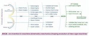
The ‘Positive Displacement’ Mechanism based Machines. The most prominent example of ‘Positive Displacement’ type mechanism is the Reciprocating piston crank mechanism, which is the most widely used mechanism for modern day I.C. Engines. “Reciprocating Piston Crank mechanism’ also known as ‘slider crank’ or as ‘four bar link mechanisms’ is the root mechanism in steam engines of yester years and modern day Petrol & Diesel Powered Engines used in Cars and for Main Propulsion Prime- Movers in Merchant Ships. Though this mechanism is very robust and the backbone of today’s I.C. Engines it has its limitations like the out of balances forces that are created in the components and most importantly the inability to deliver commercially viable ‘Variable Compression Ratio’ engines due to its complexity and cumbersomeness.
There are ‘Rotary type’ Positive displacement mechanisms too like those used in Pumps like gear pumps, snake pumps, screw pumps for pumping of viscous fluids and fossil fuels etc. However, what we see is that the rotary positive displacement so vividly used in pumps has its limitation that it cannot be been used to make I.C. Engines. This is because the fluid is not get pressurised within the machines element and this is a necessary requirement for making an I.C. Engine. It is very often considered by students of engineering that screw and gear Pumps actually compress the fluids whereas it is not the case. These pumps simply transfer fluid from suction to discharge and if the discharge is throttled or restricted the pressure in the fluid rises as it cannot go back to the suction side.
The only known ‘Rotary positive displacement’ mechanism based I.C. Engines used in a fraction of applications compared to piston crank engines, is the Wankel engine which is still used for various applications like Unmanned Ariel Vehicles and military aviation applications. There are some examples of other rotary positive displacement mechanism Like MYT (see link http://fuel-efficient-vehicles.org/energy-news/?page_id=908) and radial vane which have been experimented upon but it has never been successful. The major limitation of these mechanism is the various problems associated with it like difficulty in sealing of fluid chambers and their thermal imbalances.
There is an another set of ‘Rotary Positive displacement’ Mechanism where fluid can be pressurised within machine elements however the complexity of these mechanism makes it difficult to use it for making I.C. Engines. These are normally used in Hydraulics and known for its Variable Delivery characteristics, namely the ‘Axial Piston Pump’ which uses swashplate angularity for variation in volume and, the ‘Radial piston Variable Delivery Pump’ with a floating ring to manipulate the variation in fluid volume. We have had radially arranged piston mechanism used to make I.C. Engines for aviation purpose. We do see the said rotary positive displacement mechanism being used for fluid motors in hydraulic applications almost universally. This generally summarises the Positive displacement mechanism generally in use as compressors, pumps, fluid motors, engines and their limitations.
Rotary Dynamic/ Centrifugal Mechanism
The Rotary Mechanism are mainly used to impart Kinetic energy to fluids or from fluids to as we see in centrifugal Pumps and wind turbines respectively. There are various types of centrifugal pumps for differing applications like deep-well pumps, multistage and high pressure pumps or low pressure + high flowrate pumps, however the base mechanism remains the same. The limitations with this mechanism is the fluid slip. Unlike positive displacement mechanism (where once the fluid is entrapped within the enclosure of the machine elements like casing and rotor, of barrel and piston, it has to delivered through the discharge and cannot be sent back to suction or intake chambers) in a centrifugal mechanism the fluid can slip back to the suction side through the machine elements. Furthermore, it cannot create its own suction and needs to be assisted by some means.
A Similar application of the dynamic rotary mechanism is the conversion of energy in fluid flow by wind turbines and water turbines used as Prime-Movers for Power generation. Though these machines are very simple and easy as far as design is concerned yet there is a limitation of its energy capture efficiency, which put demand on maximising the energy capture by increasing size and hence end up being extremely large for being commercially viable.
This Mechanism being used as fuel motored engine is in a turbojet engine or a gas turbine which has great performance capability, however its limitation is that it is low on fuel efficiency. The hydro kinematic applications like in dams or producing hydro-electric power is well known application of capturing energy from fluid head using rotary dynamic mechanism based turbines however it is not suitable for trapping energy from fluid flow as in case of tidal or wave energy. We further see that the major limitation of Dynamic/rotary mechanism is that of pressure limitations. When it comes to high and very high pressure applications only positive displacement mechanisms can be used.
The implications
Machines based on these Kinematic mechanisms have existed now for over a century and have well served their purpose to mankind in mechanization. The 20th century was instrumental in the continual incremental development of machines based on the various mechanisms discussed and almost all of it happened in the western world since the beginning of the industrial revolution, however, they do not suffice for the demands of a 21st century environmental concerns. Today we need new breed of machines for diversifying our energy source from fossil fuel alternative sources like green fuels, renewable energy and with a lower Carbon Foot print so that we can unhook from fossil fuel dependency.
21st Century challenges
Indiscriminate use of fossil fuel leads to GHG emission and a very high per capita carbon footprint which is the primary cause of global warming and concrete solutions are needed to effectively check the forced climate change by humans. Reverting back to pre-machine pre-industrial age is not an option. The viable option is effective use of energy and fossil-fuel and switching over to newer sources of energy. The current generation of machines and mechanism have been explored and improved for over a century now and is over saturated and the design freeze levels (cost of research for improvement in the efficiency) of these machines are very high even for minimal gains. Researchers and scientists are trying to develop new solutions and numerous alternatives have been proposed, however these have always remained segmented and restricted to a limited application, like battery as Prime-Mover is being applied to passenger Cars and is restricted to this segmented area. It is very difficult to apply same to other transport systems like Heavy Commercial Vehicles, Aviation etc. Similarly, bio fuels are another alternative being worked upon, however this too is applicable to limited segment. It should be noticed that these solutions, if seen in context of economics, reduce use of fossil fuel thus reducing its demand to certain extent, however supply of fossil fuel remains unaffected thus creating surplus and making fuel cheaper (on use of these alternatives) and pitching these solutions against cheaper fossil fuel thus making them unviable.
The possibilities
The fossil fuel dependency of industry has been ever increasing through the last century and so is the economic structure in which livelihood of millions are dependent is based on fossil fuel Industry. Hence any disruption to fossil fuel based economy faces huge resistance to any change. The technology solution hence lay in NOT fighting fossil-fuel head on, rather to have machines that use it more optimally and efficiently and at the same time make alternative source of energy more viable.
The next step in efficient use of fossil fuel is a known technology feature which has been tried out by almost all engine industry players and is known as ‘VCR’ (Variable Compression Ratio). The difficulty is that this technological feature has never been commercially viable in engines mainly owing to the limitations of the Reciprocating Piston Crank mechanism.
Similarly, diversifying energy source from fossil fuel to renewable energy sources also requires new generation of machines with high energy capture efficiency that can tap into the flow energy in wind and tidal waters ever more efficiently. Understanding the possible solutions discussed above, the requirement today is of a new mechanism alternative which can result in better efficient fluid driven motors for power generation and make VCR engines Viable.
The Solution
It is in this background that a revolutionary solution is brought about by an invention of a new Kinematic mechanism called RVCR (Rotary Variable Compression Ratio). The invention is a Mechanism which leads to new breed of fluid handling machines which are highly efficient, compact, cheaper and with lower carbon foot print.
RVCR is a new mechanism of ‘Rotary Positive Displacement Type’ and is an addition in the field of kinematic mechanism which is a superior alternative to the ‘Reciprocating Piston Crank Mechanism’ and it combines the performance gains of the Rotary mechanisms and the efficiency gains of ‘Positive displacement’. The key characteristic of the RVCR mechanism is that it enables the VCR (Variable Compression Ratio) feature in fluid handling machines by means of variable displacement of volumes between its rotating elements. It is the ease of the mechanism over the current complex ones used for (Variable Delivery Pumps) that opens up the opportunity of use of positive displacement mechanism in fluid motors for tapping wind energy and to make VCR engines. The detailed in the mechanism is in the next section and explained in the link below’.
http://www.google.co.in/patents/US7431007
The RVCR Mechanism
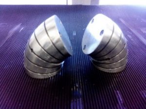
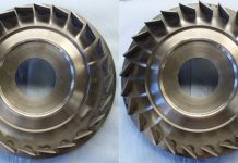
RVCR or ‘Roto-Dynamic Variable Compression Ratio’ is an invention in the field of ‘kinematic Mechanism’ by an Indian Er Mr Das that lead to the birth of new age and modern day machines. The invention of RVCR is a new addition to the world of ‘machine mechanism’ which is about entirely new set of components with novel geometry and their assembling arrangement, which enables Sequential motion of rotary elements that was never possible earlier. The root elements of the RVCR Mechanism are hereafter explained in simple terms. The RVCR geometry is about a toroidal liner (which is the shape formed by bending a straight tube such that the two ends, the top and bottom ends of are joined) meet resulting in a torus (like a hollow ring or doughnut). This hollow torus can be seen as wheel tyre of a CAR along with its rim. The hollow space inside has two pistons which are also bent with an equal curvature of the liner. The computer model of the figure of the piston is shown below and the picture of the physical (Manufactured) model is in shown.
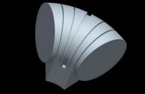
As it can be seen that the piston is not cylindrical but a bent cylinder, called a ‘vane piston’, and is placed inside the torus and the outer curved surface of the piston fits snugly into the hollow curved tubular volume of the Liner, where both the piston can slide and rotate inside the torus. The two ‘vane pistons’ divide the volume inside the torus into two chambers.
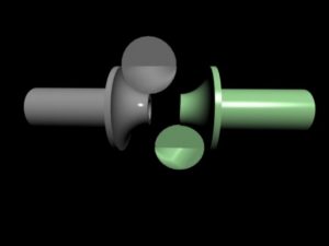
When one ‘vane piston’ is kept stationary, the other is being rotated inside the torus the volume between the vane piston is altered such that the volume ahead of the vane piston in the direction of rotation is reduced and the volume behind is increased. The schematic diagrams of the elements of the RVCR mechanism is depicted in below figures. Here in fig1 the two circular plates can be seen fixed to a curved surface at the end of a tubular sleeve. One quarter of the edge of each circle is fixed to the curved disc at the end of the sleeve tube. This is referred to as the sleeve Vane fitting. The two sleeve Vane fittings are seen mirror image of each other and place coaxially.
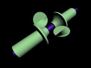
The next fig 2 shows the two sleeves mounted on a coaxial shaft (Blue coloured shaft).
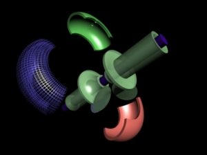
The below fig3 shows 3part outer covering in an exploded view.
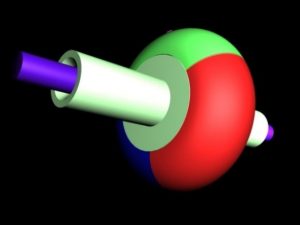
Fig 4 below shows the three-part outer shell encasing the curved disc end of the sleeve.
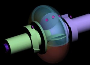
The figure 5 below shows the inner arrangement of the assembly. It can be noted that the sleeves in are fitted with two negative cams. The purple colored circles are depiction of valves.
The Vane Pistons move in a pattern where initially one Vane Piston (say VP1) rotates independent of the other (Say VP2) which is held stationary. While VP1 is rotating, the sleeve on which it is fitted rigidly also rotates and the sleeve is coupled to the central shaft. When the Rotating VP1 reaches a near the stationary piston VP2 then, the sleeve on which it is fitted clutches on with the rotating shaft and rotates along with VP1 with same rpm and thus the rotating piston does not collide with the stationary one. Next the previously rotating piston VP1 reaches the position of the previously stationary piston and it is declutched from the central shaft and is now held stationary by break shoes. The previously stationary piston VP2 now rotates until it reaches the proximity of the now stationary VP1 and the pattern is repeated. The mechanism converts the alternate rotation of two pistons into a singular continual rotational output by clutching the sleeve of the rotating ‘Piston-Vane’ to a continuous centralised shaft.
We see that as one of the ‘Piston Vane’ rotates it compresses fluid or Air ahead of it against the stationary vane and closer the rotating vanes gets to the stationary vane, higher the compression. The most significant innovative feature is that the RVCR technology allows engines to achieve analogous variation in the compression by altering the start point of the stationary ‘Piston-Vane. This is done by controlling the start of rotation of the stationary ‘Piston Vane’ relative to the rotating Poston. If the stationary vane starts only when the rotating piston has reached very near to it, then the Compression Ratio Is high and vice versa.
The compression ratio can be varied to suit different fuels (diesel, petrol, LPG, LNG, CNG, biofuel) in the same engine. The engine can change its compression ratio from the lower end for petrol and gas, to high compression ratio (more compressed) for diesel use resulting in a car with a multi-fuel engine. Furthermore, the dynamic real-time setting of the compression ratio enables the RVCR engine to deliver the highest possible efficiency in fuel, power allocation and control of emissions. The mechanism, patented in India & USA (patent No. US 7,431,007 B2, Oct 7, 2008) and in various countries world-wide. See below link.
http://www.google.co.in/patents/US7431007
RVCR Design
The RVCR mechanism is about a unique arrangement of mechanical links and their pairs for making new machines with fewer and simpler components that can achieve sequential compression and expansion of gases by decreasing and increasing of enclosed volume requisite for various thermodynamic processes and cycles used in fluid powered and fluid motored Machines, thence RVCR is a seed mechanism for various downstream engineering products like highly efficient Compressors, Pumps, wind/hydro motors and the most significant of all ‘VCR I.C. Engines’, making RVCR next progressive mutation in Machine Mechanism. RVCR is the 1st Mechanism Patented in 23 countries globally making RVCR the indigenous technology providing a unified solution to the 21st century challenges and to unhook economy from fossil fuel dependency.
(The technology feasibility, and technical aspects to be covered in Next Article)


