


")


A turbocharger is a forced induction device that recovers engine waste heat in order to increase performance and efficiency in a combustion engine.
This is accomplished by utilizing otherwise wasted energy from the engine exhaust to compress the incoming air charge. A turbocharger draws in ambient air and compresses it, ultimately increasing the intake manifold pressure. The result is a higher density of air in the cylinders, raising the performance potential.
The components of a simple turbocharger include:
- Compressor housing
- Compressor wheel (compressor)
- Turbine housing
- Turbine wheel (turbine)
- A common shaft connecting the turbine and compressor wheels.
The compressor and turbines of a turbocharger rotate in unison – that is, both wheels rotate with exactly the same angular velocity. Therefore, for any force acting upon the turbine, an equal force is acted upon the compressor. This is the basis for recovering waste heat from the engine exhaust. As high velocity, high temperature gases are expelled from the combustion chamber, they travel from the exhaust manifold through the turbine housing. A portion of the energy contained in these gases is than transfered to the turbine and therefore compressor of the turbo. The turbine and compressor housings are isolated from one another – there is therefore no mixing of air and exhaust gases.
The geometry of the turbine is optimized to capture energy from the exhaust stream, while the compressor is optimized to pressurize the incoming air charge. In other words, compressor and turbine geometries (shape, size, fin design) are characteristically designed for separate purposes and are therefore different in appearance. The thermodynamic process by which waste energy is converted into usable mechanical power results in a temperature differential between the inlet and outlet of the turbine housing. While the turbocharger is in operation, the temperature of exhaust gases at the inlet of the turbine housing will always be greater than at the outlet of the turbine housing. The greater the temperature difference, the more energy extracted by the process.
A turbocharger increases performance by forcing air into the combustion chamber of each cylinder, increasing the volumetric efficiency. This is opposed to a naturally aspirated process, where air is drawn in by the vacuum created as the piston descends on the intake stroke. The greater volumetric efficiency of the forced induction process results in a denser charge of air and therefore higher quantity of air molecules present in the combustion chamber prior to the compression stroke. The greater amount of oxygen molecules present therefore allows for a greater quantity of fuel to be injected, resulting in higher power outputs.
The pressure a turbocharger creates is commonly referred to as boost – to make more boost is to create a greater manifold pressure (the pressure of the intake manifold is roughly equal to the pressure of air in the combustion chamber at the end of the intake stroke). Because compressing air proportionally increases its temperature, intercooling is common on turbocharged engines to further increase efficiency and performance potential. The efficiency of a turbocharger is not constant; efficiency can vary considerably depending on operating conditions such as speed and load.
A “large” turbo typically provides top-end power and higher airflow potential, while a “small” turbo exhibits quick spooling characteristics at the expense of lower overall airflow at higher engine speeds. In single turbo applications, selecting a turbocharger is a balancing act of meeting airflow requirements and minimizing turbo lag.
Turbocharger A/R Ratio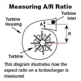
The A/R ratio of a turbocharger goes by many names, including “aspect ratio”, “area to radius ratio”, “air ratio”, and “area ratio”. All these terms are synonymous with one another and refer to the ratio of the area of the turbine/compressor inlet to the distance between the centroid of the inlet and the center of the turbine/compressor wheel.
A/R ratios are typically discussed in reference to turbine housings as the A/R ratio of the turbine housing significantly impacts turbocharger performance, whereas compressor performance is less sensitive to changes in compressor housing A/R ratios. As a result, turbine housings are generally characterized by the A/R ratio, while the compressor side of the turbo is distinguished by the exducer/inducer diameters and trim.
Generally speaking, turbine housing A/R ratios exhibit the following characteristics:
Large A/R Ratio – The larger the A/R ratio, the slower the turbo spools (more lag, slower response). However, a large A/R ratio yields greater top end performance potential and efficiency in addition to lower backpressure and higher flow capacities.
Small A/R Ratio – The smaller the A/R ratio, the quicker the turbo will spool (less lag, better response). This is at the expense of flow capacity and lower performance overall. A turbine housing with a small A/R ratio will suffer from greater pumping losses, increased backpressure, and the turbocharger may choke on the top end. The flow velocity of exhaust gases into the turbine housing is higher.
Controlling Boost with a Wastegate
On a standard turbocharger (non-VGT), maximum boost pressure is controlled by a device called a wastegate. The wastegate is essentially a valve that can be internally or externally integrated into the turbine housing. When a predetermined boost pressure is realized, the wastegate opens and allows exhaust gases to bypass the turbine. In effect, the wastegate controls turbocharger outlet pressure by metering the amount of exhaust flow across the turbine. Exhaust gases that bypass the turbine housing expel directly into the exhaust system at the turbine outlet.
Variable Geometry Turbochargers(VGT or VTA)
A variable geometry turbocharger features a series of operable vanes in the turbine housing that vary its geometry, increasing or decreasing the A/R ratio as necessary to provide optimal performance and efficiency at any combination of speed, load, and pressure. The vanes, which are actuated electronically, hydraulically, or by vacuum, open and close as commanded by the PCM in order to build or maintain boost pressure as necessary. This effectively allows a single turbocharger to display the characteristics of both a small and large turbo simultaneously.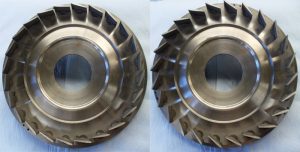
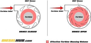
With the vanes in the closed position, the effective size of the turbine housing is decreased and the A/R ratio reduced. In this position, the turbocharger may spool rapidly since the exhaust gases are more concentrated at the turbine wheel, in effect compensating for low exhaust flow.
As the vanes gradually open, the effective size of the turbine housing is enlarged and A/R ratio increased. In this position, the turbocharger can manage higher exhaust flow rates, exhibiting good overall performance characteristics without choking from high backpressure. A VGT turbo also uses the variable vane system in place of a wastegate – instead of using a valve to bypass exhaust flow, the vanes open, reducing the flow velocity and concentration of exhaust flow on the turbine wheel.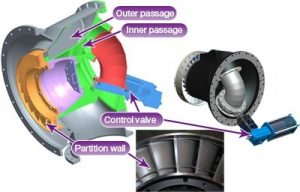
In addition to providing an optimal A/R ratio based on current operating conditions (load, speed, demand, etc), a VGT turbocharger can be used an exhaust brake by closing the vanes during acceleration, effectively increasing backpressure in the same manner that a typical exhaust brake would. OEM “exhaust brakes” are more often than not simply a selectable mode.
VTI technology & slow steaming
Ship’s engineers normally employ turbocharger cut-out during slow-steaming, so that in an engine equipped with several turbochargers one of them is stopped at slow engine speed. Then, when say one of four turbochargers is stopped, exhaust gas is distributed to the remaining three, which serves to increase the scavenging air pressure and improves fuel efficiency. MHI-MME set out to redesign the turbocharger hardware to improve on that operational procedure and came up with their VTI technology.
This system which was developed for the manufacturer’s MET turbocharger series, 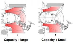 incorporates a gas inlet passage, which is equipped with an on-off valve. This changes turbine capacity in two stages by admitting the exhaust gas into two separate concentric segments of the nozzle ring. When the vessel is operating in slow steaming mode, the scavenging air pressure of the main engine is increased by closing the on-off valve, thereby decreasing the fuel consumption rate and CO2 emission levels.


")


