 The previous article on RVCR Mechanism covered the various types of machine Mechanism, their typical usage in engineering applications as per suitability and their various limitations and it also introduced the basics of the novel RVCR mechanism, its components and the sequential motion of the Piston Vanes within the torus.
The ‘Piston-Vane’ was depicted as a simple surface of circular geometry that was fitted at one end of the sleeve with half of its surface protruding and extending out of the end surface so that when a similar Sleeve and ‘Piston Vane’ Fitting is kept as a mirror image the two ’Piston Vane fitting can be made to rotate with their centre in a same plane. The basic assembly was also depicted showing the two sleeves mounted on a central shaft and how it is encased within an outer shell. A consolidated figure of all the depictions is show below in Fig 1.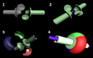
Hereon we pick up from where we left the last time and realise the actual geometry of the components like the ‘Piston Vane’ etc. The CAD Model showing the geometry of the ‘Piston Vane’ is shown in Fig 2. of a sleeve Vane fitting subassembly where the light grey coloured Piston Vane (the shape of a bent cylinder with piston ring grooves) is rigidly fixed to sleeve end surface that is contoured in a shape to receive the piston vane surface). The Piston is rigidly fixed on to the Sleeve end face which is so curved to receive the piston curved surface. The sleeve end surface covers one quarter of the ‘Piston Vane’ curvature and is called the Inner Liner Quarter. The inner Quarter surface contour can either be machined on the sleeve end surface or a separate insert with the desired shape can be fitted at the end of the sleeve cylinder. Fig 2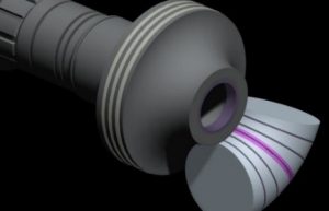
CAD Model: – ‘Sleeve Piston-Vane’ assembly.
Below Fig 2 is the CAD Model of intermediate rotor assembly constituting of the two Sleeves with their Vane piston fitting put together and covered with a casing. (The model of the casing is made transparent such that both the Piston Vane are visible and the Cooling fins of the outer casing is slightly visible).
Fig 3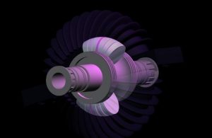
CAD Model of Inter-Rotor assembly
‘The models were developed in Pro E software and the sleeves also show case the grooves and splined end. The sleeve is a hollow cylinder with a bore to receive the central shaft and the two sleeves are mounted on this central shaft on bearings. Next Fig is that of the lower half of the outer casing which forms the outer shell of the torus chamber. The upper half has a similar geometry and is bolted on to the lower half.
Fig 4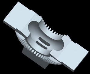
CAD Model of – Casing Lowe Half
The below is a CAD model assembly of the Inter-rotor assembly with the ‘Piston Vane’ encompassed within the Upper casing half and lower casing half.
Fig 5
CAD Model – Inter Rotor Assembly.
During the sequential operations of the Vane Pistons the stationary piston plays the role of the cylinder head against which the rotating piston compresses the Air, or air fuel Mix, hence eliminating the need of a separate cylinder Head. Similarly, the dedicated crank case is also eliminated as it is integrated with the casing.
A cam is fitted on the Sleeve rigidly and the cam has it profile corresponding to the position of ‘Piston-Vane’ Inside the toroidal chamber inside and hence as the sleeve rotates the ‘Piston Vane’ inside the chamber rotates and at the same time the angular position of Piston Vane corresponds to the cam fitted externally hence the ‘Piston Vane’ inside the casing is controlled by reading its Position externally on sleeve body, to which it is rigidly fixed. These cams are called the positioning cam or Pos Cams and a follower of the Cam is so placed that the cam profile reaches it before its Corresponding ‘Piston-Vane’ (fitted on the sleeve on which the cam is fitted) can ram against the stationary vane inside the torus. As the follower is actuated ahead of the rotating ‘Piston-Vane’ nearing stationary and at the same time the actuation is transmitted across to the other end sleeve with stationary ‘Piston-Vane’ and activates clutching against between the stationary sleeve and the rotating central shaft to which the rotating Sleeve is already clutched in thus both sleeves now rotate simultaneously. Now that the stationary ‘Piston-Vane’ is rotating its cam profile reaches the follower and actuates the opposite sleeve to clutch out as the previously rotating Sleeve reaches the point where the ‘Pistons Vanes are held stationary and to engage brakes.
Hence it can be seen that the Positioning Cam and the angular position of its profile with respect to the ‘Piston Vane’ on the sleeve and its follower position decides when both the piston rotate together and the amount of angular gap between them. Thus the compression pressure is defined by the cam profile and the profile has varying profile angle along an axis through which the follower can be shifted to achieve Variable compression ratio.
The RVCR mechanism delivers lighter, smaller engines and eliminates connecting rod and entablature structure. The Vane Pistons in RVCR is a double acting one and where one end face of the piston forms a boundary of volume that reduces and the other end face forms the boundary of a volume that increases.
VCR Engine evolution
We have known of engines as either Petrol or diesel since the beginning, however there were a few who wondered why engines are fuel specific and this lead to experimentation on “VCR” engines but even about a century since Sir Harry Ricardo 1st attempted VCR engines in 1920, it could never be realised due to limitations of the ‘Kinematic four bar link Mechanism’. RVCR can achieve the requisite variations in Volume with ease and makes ‘VCR’ engines a reality.
The mechanism enables intricate control on internal combustion parameters by enabling analogues variation in compression ratio throughout the desired range, required for differing fuels, starting form light fuels like LNG to high density HFO. The compression pressure manipulation control complements existing qualitative & quantitative fuel Injection control to output an engine which can burn multiple fuels. The peak pressure control and variation leads to finer fuel efficiency throughout the load range for any specific fuel and thus providing for peak pressure control for differing load conditions, like increase in compression ratio during Idling and reduction during excessive loads for turbocharged engines. The peak pressure control and thus temperature control provisions for better emission control.
The number of strokes in engines based on the invented mechanism is half of that of conventional reciprocating engines and hence the 2 and 4 stroke equivalents are single and dual stroke, thus the mass requirements of flyweights, for negating large variations of the turning moments throughout the cycle is reduced. The balancing of the engine rotating mass is simplified owing to the elimination of reciprocating pistons and rigidly fitted pistons eliminate the second order vibrations namely the chattering of pistons floating on Gudgeon during fuel explosion.
RVCR is a new superior ‘Rotary Positive Displacement Mechanism’ mechanism which enables control on the degree of variation in volumes during operation that breaks-open current boundary limitations of performance and efficiency characteristics. The ‘VCR’ engines are not simply about using two different fuels in the same engine but rather it is about enabling use of any choice of fuel in the same engine depending on availability, cost or need, hence opening up new possibility where green fuel can compete with fossil fuels. Similarly, It also opens possibilities of newer machines with capabilities that bring in a fundamental change in societal priorities. Today wind motors which are generally 3 blade wind turbine, which has low ‘Power Take Off’ and ‘Energy Capture coefficient’ due to limitations of the rotary mechanism. The RVCR mechanism bring in a positive displacement mechanism perspective to wind energy power generators, improving efficiency and at the same time reducing ‘installation and maintenance cost’. This makes renewable energy a far more commercially viable power source, thus tilting the energy supply balance towards green energy. RVCR is the next progressive mutation in Kinematic Mechanism that combines the gains in ‘efficiency’ from Positive Displacement Mechanism with the ‘performance’, ‘simplicity’ and ‘compactness’ characteristics of a rotary mechanisms, and initiates the next evolutionary leap in machine characteristics, features and functionalities. RVCR mechanism is applicable to a broad spectrum of Industrial applications like ‘Prime-Movers’ for ‘Energy/power generation, Transportation, agro and drives for various fluid handling machines’ and ‘Utilities’ like Pumps, Compressors, fluid Motors in Hydraulic, hydro, breweries, fluid metering devises in pharma, petrochemicals etc. These machines are generically classed as “fluid handling machines”, i.e. either fluid powered/driven/motored or fluid pumping/driving machines.


